Building a Secure PIN Input System with Raspberry Pi Pico and OLED Display
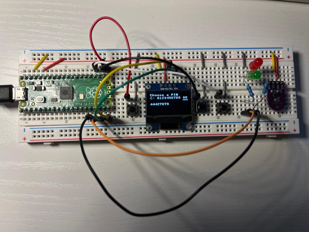
In this tutorial, we’ll walk you through creating a simple PIN input system using the Raspberry Pi Pico, an OLED display, and physical buttons. The PIN system allows the user to set and enter a PIN with the help of buttons and display feedback on an OLED screen. We’ll be using the Raspberry Pi Pico’s GPIO pins, I2C communication for the display, and basic input logic to interact with the system.
Hardware Requirements:
- Raspberry Pi Pico
- OLED display (SSD1306)
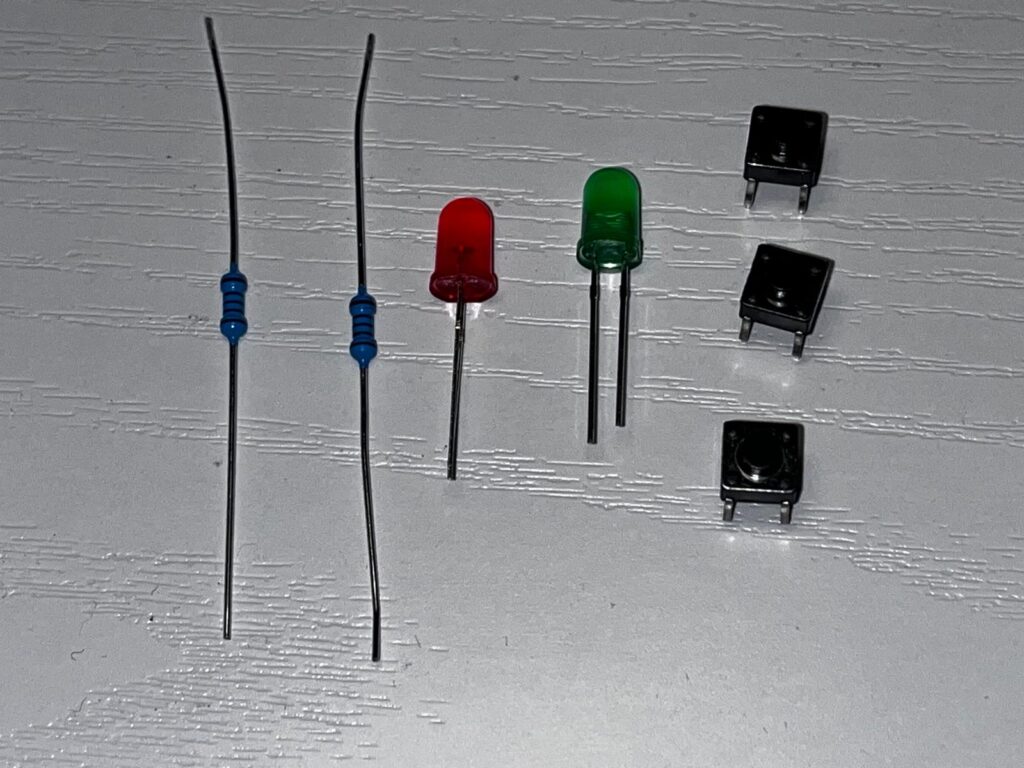
- 3 Push buttons (for navigating the PIN input, deleting digits, and confirming the PIN)
- 2 LEDs (optional for visual feedback)
- 2 330Ω resistor for the LEDs
- Jumper wires and a breadboard

Wiring:
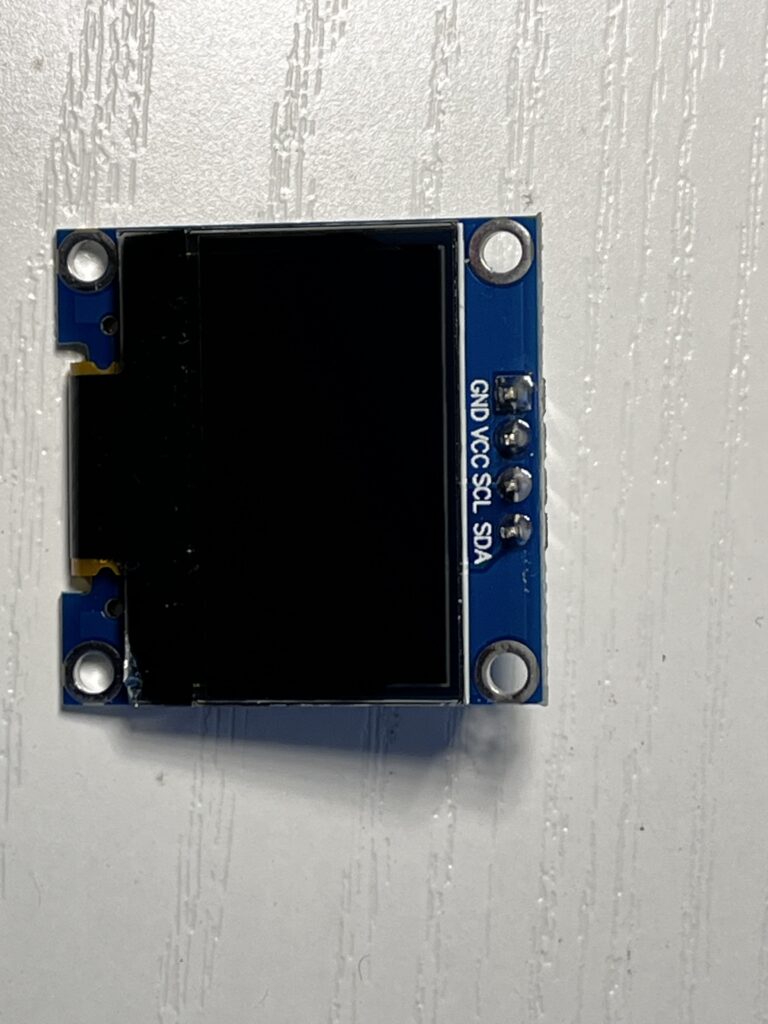
- OLED Display (SSD1306):
- Connect SDA pin of the display to GPIO 14 (Pin 19).
- Connect SCL pin of the display to GPIO 15 (Pin 21).
- Connect VCC to 3.3V and GND to ground.
- Buttons:
- Button for incrementing the number (GPIO 16 – Pin 21).
- Button for decrementing the number (GPIO 17 – Pin 22).
- Button for confirming the PIN (GPIO 18 – Pin 24).
- LEDs:
- Green LED (GPIO 13 – Pin 13).
- Red LED (GPIO 12 – Pin 12).
Wiring details:
| Raspberry Pi Pico Pin | Component | Description | Additional Connections |
|---|---|---|---|
| GPIO 14 (Pin 19) | SDA (OLED Display) | Data line for I2C communication with OLED display | Connect to OLED SDA pin, Ground to GND, +3.3V to VCC |
| GPIO 15 (Pin 21) | SCL (OLED Display) | Clock line for I2C communication with OLED display | Connect to OLED SCL pin, Ground to GND, +3.3V to VCC |
| GPIO 13 (Pin 13) | Green LED | Indicator LED for success (flashes green) | Connect an appropriate resistor (220Ω-330Ω) in series with the LED’s anode (positive leg); cathode (negative leg) to GND |
| GPIO 12 (Pin 12) | Red LED | Indicator LED for errors (flashes red) | Connect an appropriate resistor (220Ω-330Ω) in series with the LED’s anode (positive leg); cathode (negative leg) to GND |
| GPIO 16 (Pin 21) | Button (Up) | Button to increment the selected digit | One side of the button to GPIO 16, the other to GND (with internal pull-up resistor enabled in the code) |
| GPIO 17 (Pin 22) | Button (Down) | Button to decrement the selected digit | One side of the button to GPIO 17, the other to GND (with internal pull-up resistor enabled in the code) |
| GPIO 18 (Pin 24) | Button (Select/OK) | Button to confirm the selected PIN value | One side of the button to GPIO 18, the other to GND (with internal pull-up resistor enabled in the code) |
| 3.3V Pin (Pin 36) | Power | Supplies 3.3V to OLED display and LEDs | Connect to VCC pins of OLED and LEDs |
| GND Pin (Pin 38) | Ground | Common ground for the system | Connect to the GND of all components (OLED, buttons, LEDs) |
Notes:
Power: The OLED and LEDs both require a 3.3V power supply. This is provided by the Raspberry Pi Pico’s 3.3V pin.
Resistors for LEDs: Use current-limiting resistors (220Ω to 330Ω) in series with the LEDs to prevent them from burning out due to excessive current.
Button Pull-ups: The internal pull-up resistors of the Raspberry Pi Pico are used to detect button presses. This means one leg of each button goes to the GPIO pin, and the other to GND. When the button is pressed, the connection is pulled to LOW (GND).
Software Overview:
The program uses MicroPython and the machine module to interact with the GPIO pins, control the OLED display, and handle button inputs. The logic is built to:
- Display a cursor for selecting digits.
- Allow the user to increment or decrement the digit using buttons.
- Enter the PIN by pressing the “OK” button.
- Flash a green LED for valid actions and a red LED for error messages.
Code Explanation:
pythonCopyEditfrom machine import Pin, I2C
import ssd1306
import time
import random

# Initialize I2C and OLED display
i2c = I2C(1, scl=Pin(15), sda=Pin(14))

led_green = Pin(13, Pin.OUT)
led_red = Pin(12, Pin.OUT)

#error message
error_message = ""

# Initialize OLED display
display = ssd1306.SSD1306_I2C(128, 64, i2c)

# Initialize buttons
button_up = Pin(16, Pin.IN, Pin.PULL_UP)  # Button to increase the number
button_down = Pin(17, Pin.IN, Pin.PULL_UP)  # Button to decrease the number
button_select = Pin(18, Pin.IN, Pin.PULL_UP)  # Button to confirm the number

# Function to flash the green LED
def flash_green():
    global error_message
    error_message = ""
    led_green.value(1)  # Turn green LED on
    time.sleep(0.1)
    led_green.value(0)  # Turn green LED off

# Function to flash the red LED with error message
def flash_red(err_message):
    global error_message
    error_message = err_message
    print(error_message)  # Display the error message
    led_red.value(1)  # Turn red LED on
    time.sleep(0.1)
    led_red.value(0)  # Turn red LED off

# Function to enter a PIN
def enter_pin():
    display.fill(0)
    code_completed = 0
    pin = []
    curseurPosition = random.randint(0, 9) + 1
    curseurValues = ['del', 0, 1, 2, 3, 4, 5, 6, 7, 8, 9, 'ok']
    curseurDisplay = ['__', '   _', '    _', '     _', '      _', '       _', '        _', '         _', '          _', '           _', '            _', '              __']

    current_digit = 1

    while code_completed == 0:
        if not button_up.value():
            display.fill(0)
            curseurPosition = curseurPosition - 1
            if curseurPosition == -1:
                curseurPosition = 11
            time.sleep(0.2)  # Anti-rebounce
            flash_green()
        elif not button_down.value():
            display.fill(0)
            curseurPosition = curseurPosition + 1
            if curseurPosition == 12:
                curseurPosition = 0
            time.sleep(0.2)  # Anti-rebounce
            flash_green()
        elif not button_select.value():
            display.fill(0)
            if curseurPosition == 0 and len(pin) > 0:
                pin.pop()
                time.sleep(0.2)  # Anti-rebounce
                flash_green()
            elif curseurPosition == 0 and len(pin) == 0:
                flash_red("PIN is empty")
            elif curseurPosition == 11 and len(pin) >= 4 and len(pin) <= 8:
                time.sleep(0.2)  # Anti-rebounce
                flash_green()
                code_completed = 1
            elif curseurPosition == 11 and len(pin) < 4:
                time.sleep(0.2)  # Anti-rebounce
                flash_red("min 4 numbers")
            elif len(pin) < 8:
                pin.append(curseurValues[curseurPosition])
                curseurPosition = random.randint(0, 9) + 1
                time.sleep(0.2)  # Anti-rebounce
                flash_green()
            else:
                flash_red("max 8 numbers")

        # Display current PIN on OLED
        display.text('Choose a PIN', 0, 0)
        display.text("<- 0123456789 OK", 0, 10)
        display.text(curseurDisplay[curseurPosition], 0, 14)
        display.text(''.join(map(str, pin)), 0, 30)
        display.text(error_message, 0, 55)
        display.show()
        time.sleep(0.1)

    return ''.join(map(str, pin))

# Call the function to enter the PIN
pin = enter_pin()
print(pin)
Repository:
https://github.com/ericbzotti/pico-pin-entry
How It Works:
- I2C and OLED Setup:
- The OLED display is initialized using the I2C interface. The screen is used to display the PIN input process and feedback messages.
- Button Inputs:
- There are three buttons:
- One button to increment the selected digit.
- One button to decrement the selected digit.
- One button to confirm the PIN.
- There are three buttons:
- PIN Input:
- The user navigates through the digits and selects the desired PIN by pressing the respective buttons. The system allows entering a PIN between 4 and 8 digits long.
- Feedback is provided using green and red LEDs.
- Error Handling:
- If the PIN is too short (less than 4 digits), an error message is displayed, and the red LED flashes.
- If the PIN is too long (more than 8 digits), another error message appears.
- Display Update:
- The OLED screen is constantly updated to show the selected digits and the current state of the PIN input.
Conclusion:
This project demonstrates how to build a simple, interactive PIN input system with a Raspberry Pi Pico. You can expand on this system by adding more complex features such as encryption, multi-step authentication, or integration with other devices.
Feel free to modify the code for your needs, and enjoy building your own secure PIN input system with the Raspberry Pi Pico!